Techniques of Molecular Modelling: Molecular Visualisation
Historical Preamble
 |
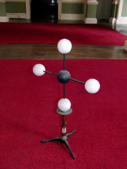
Molecular Visualisation originated from the physical models of
molecules often used in conjunction with lectures, the grand
daddy of which was constructed by August Wilhelm von Hofmann as early as
1860 whilst lecturing at what was the precursor to the modern
Chemistry department at Imperial College (and who also introduced
the still familiar colour scheme). Note the planar carbon
(tetrahedral carbon was some years away!).
Josef Loschmidt introduced the spacefill form of
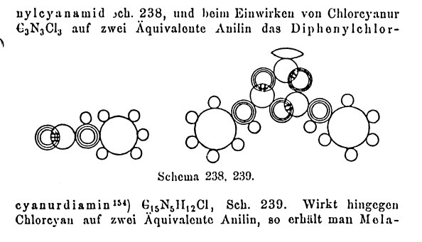
representation still in use today to visualize molecules, and also of bond types representations (single, double, triple) in a booklet published in 1861. We can judge
how accurate his visualisation was by comparing his diagram (of
an aromatic triazine) with a modern computer generated model.
Note that the cyclohexatriene structure for the benzene nucleus
itself (as proposed by Kekulé) was still some four years into the
future at that point! (there is still controvery and debate about
whether the representation shown here fully anticipates Kekulé or
not. It certainly does for the 1,3,5,-triazine ring). Loschmidt's
diagrams are key because he introduces (implicitly) the idea that
different atoms have different sizes. It was not until 1873 that
van der Waals formalised the idea of
atomic radii (inferred from his equations of state). These radii
are now the basis of all molecular visualisation (see blog here).
|
 |
|
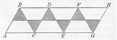 Following the recognition of the tetrahedral nature of saturated carbon in 1874, Hermann Sachse in 1890 using only trigonometry, derived the non-planar chair and boat conformations of cyclohexane and the axial and equatorial positions of the hydrogens. He even encouraged readers of his articles to construct a paper model to help them visualise this! Molecular visualization was well and truly born (except that no-one recognised the significance of Sachse's work, and he died in obscurity in 1893!)
Nowadays, molecular visualization is almost entirely accomplished using computers. What you will see in the lecture comprises "state-of-the-art" computer technology. In this demo, we will switch on the stereoscopic lecture theatre projection system. The computer generates two separate images of the molecule in question, and via the dual-channel graphics card, sends each to a different projector. The projection uses circularly polarized light reflected off an alumina-coated screen which preserves this polarization. The direction of polarization is different for the two projectors. The polarized glasses you will have been issued with also filter only one sense of polarization each; in effect the left eye sees only one projected image, the right the other. The brain then combines this information to generate its own perceived 3D image. An example of this technique as applied to one of the Laboratory experiments can be viewed here.
A second technique is also demonstrated here, using a program called Jmol to script annotations to the structure, in this case highlighting particular bonds, lengths and angles. The scripts are invoked using in-lined buttons in this case. Jmol is not (yet) Stereo-enabled, so a different program is used to enable this (DS Viewer Pro). Later in the course, animations (in stereoscopic display) will be used to enhance the visualisation process.
This model relies exclusively on effective visualisation. It is said to be the most famous scientific diagram of the 20th century! Even so, it took 3-4 years after its publication in 1953 before comprehension dawned more widely. Perhaps the lack of a readily available model which people could see in their own office did not help! Even now, its a challenge to build this from commercially available plastic models! And the coordinates provided do not help much unless you are a very experienced crystallographer.
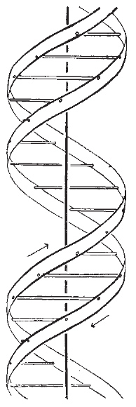
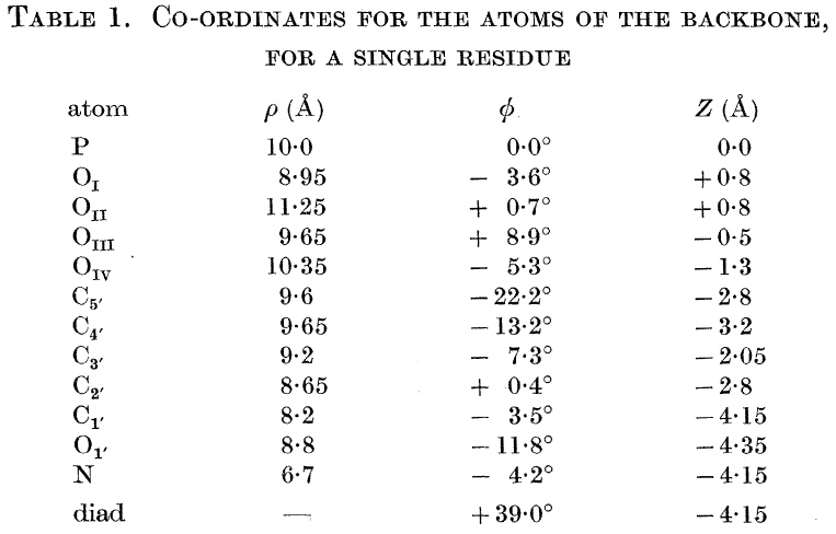
We will return to this later in the course, but I ask one question at this stage. How did Watson and Crick know that the helix was right handed?. The answer (in part) lies in van der Waals radii!
The environmental impact of chemicals is of major contemporary concern. When a new herbicide is being developed, one of the very first properties that must be understood is the likely persistence of the substance in soil. As part of a screening program, two closely related potential herbicides were found to have unexpectedly different stabilities in water, one surviving hydrolysis for hours, the other only for a minute or so. There was clearly an important need to understand this behaviour so that some design control could be exercised over this property.
The mechanistic chemists had already established that the critical center was the O-C-O group, in which cleavage of one C-O bond was the important step. In modelling this system, some important early strategic decisions have to be taken. Is the reactivity related to some intermolecular property involving say interaction with water, or is it some structural feature of the molecule itself? Some knowledge of chemistry (the "anomeric" effect) suggests that intramolecular interaction of the C-O bond with the adjacent oxygen electron lone pairs is likely to be important, which may in turn affect say the C-O bond strength and hence its length. This in turn rules out simple molecular mechanics (MM) as the first line of attack, since this is principally a method that does not deal easily with electrons and their wavefunctions. A quantum mechanical (QM) approach should work, but the relative size of the molecule, and its potential conformational complexity implies a major task. Background literature searching and reading shows moreover that QM methods have had a checkered history in dealing with anomeric effects! Its time for a exploratory approach by inspecting the crystal structure.
Using molecular visualisation soon reveals that the solvolytically unstable isomer (1, lhs) has two quite different C-O bond lengths, whereas the relatively stable form (2, rhs) shows almost no difference in these lengths. Thus (1, lhs) is well on the way to breaking a C-O bond, even with no water getting in on the act. Thus this really does appear to be an intramolecular and not an intermolecular problem, where analysing a single structural feature can give great insight into the structure-activity relationships.
|
Unstable Isomer (twist boat)
|
Stable Isomer (chair)
|
|
|
|
Firstly, you notice that the conformations of the two 7-membered rings are quite different, but one common aspect is that in both cases the aryl group is "equatorial",
an orientation generally preferred on steric grounds. This "locking" of the 7-ring then induces a particular angular relationship between each C-O bond and the lone pairs of the other oxygen atom.
We know that this property should be important from our reading about the "anomeric" effect. Although we cannot easily directly measure angles involving lone pairs, we can "idealize" these with two
dummy atoms arranged tetrahedrally around each oxygen atom. By doing this, we discover that for the stable compound, these idealised lone pairs are never quite "antiperiplanar" to the opposite C-O bond (164°)
With the unstable isomer however, one particular lone pair is found to be more closely "antiperiplanar" to the elongated C-O bond (174°), a classical manifestation of the anomeric effect.

Armed with this highly focussed conformational interpretation of our reactivity, we could now go on to design new variants, hopefully with the particular properties we want.
Literature Citations. Isoxazolinyldioxepines. Part 1. Structure-Reactivity Studies of the Hydrolysis of Oxazolinyl-dioxepin Derivatives, P. Camilleri, D. Munro, K. Weaver, D. J. Williams, H. S. Rzepa and M. Z. Slawin, J. Chem. Soc. Perkin Trans. 2, 1989, 1929. DOI: 10.1039/P29890001929
The so called Pirkle compound is much used as a chiral resolving and nmr shift reagent. In its optically active form, it will help to resolve racemic mixtures of chiral molecules by binding slightly differently with each of the two enantiomers of say an amino acid. Such chiral resolution is of paramount importance in the development of a new drug; the Thalidomide pregnancy pill case arose because of incomplete separation of two such enantiomers, one of which turned out to be toxic to the foetus.
But what sort of intermolecular interactions are involved in the binding process? The simple truth is that for the Pirkle reagent, no-one really knew until recently. Intermolecular interactions can be quite difficult to calculate accurately, especially for a molecule that size and the quickest and most direct way to probe this question is to look at the crystal packing structure if it can be measured. A search of the Cambridge crystal structure data base revealed that although no structures between the Pirkle reagent and chiral molecules had been reported, the structure of the racemic reagent itself had already been determined as part of a study on triboluminescence (the crystals emit purple light when you grind them!). The authors conclusion was that a highly unusual hydrogen bond was formed between the -OH group of one molecule and the F3C- group of another. But a small alarm bell sounds at this point. The crystallographers had not actually located the position of the hydrogen atom, they had assumed it could only sit between the O and the F. Could they be mistaken? Visualization enables this assumption to be easily tested.
The effect of the crystal lattice diagram can initially be overwhelming, the trees being well and truly hidden by the wood. The tools offered by the molecule editor make a very good wood-cutter, and soon the unique interactions involved can be displayed on the screen. Immediately apparent is that an alternative explanation involving an interaction between the OH group and the π-face of an adjacent molecule is feasible. This hypothesis was rapidly confirmed by explicitly locating the vital hydrogen atom, both in the original racemic crystal and in the optically active form (above). Many profound implications follow from this discovery. It has helped focus on the role of π-facial hydrogen bonding in protein interactions, it has now been discovered as a common feature of certain types of silanols, phenols and amines and it occurs in inclusion compounds known as calixarenes. The implications for modelling are also significant. By their very nature, most molecular mechanics methods would not reproduce the phenomenon. Moreover, the unexpected orientation of the OH bond resulting from π-facial interaction sets up specific "stereoelectronic" interactions in the molecule which profoundly affect calculated quantum mechanical properties such as electrostatic potentials, often used to predict intermolecular interactions. Thus much new insight and direction is given to a project, the germ of which was started by 3D visualization of a structure which revealed detail that others without such a tool had missed.
Literature Citations. A. M. Sweeting and A. L. Rheingold, J. Chem. Phys, 1988, 93, 5648; π-Facial Hydrogen Bonding in the Chiral Resolving agent (S) 2,2,2-Trifluoromethyl-1-(9-Anthryl)ethanol and its Racemic Modification, H.S. Rzepa, M. L. Webb, A. M. Z. Slawin and D. J. Williams, J. Chem. Soc., Chem. Commun., 1991, 765. DOI: 10.1039/C39910000765
Fast forward to next installment of this story
Molecular self-assembly of Nanobiotics: Some of the most convincing "nanoscale" molecular engineering has been carried out by Reza Ghadiri's group. They have created cyclic peptides which act as bacteriostatic agents by inserting into the cell wall, and allowing all the water inside to escape. The following cyclic peptide is known as cyclic -PHE-ALA*-PHE-ALA*-PHE-ALA*-PHE-ALA*- (* indicates the un-natural amino acid configuration).
The key breakthrough was "engineering" the nanoscale device to stack correctly so that water channels form in the lattice structure. If amino acids with identical chirality are used to form the cyclic peptide (isotactic), the stacking does not exhibit this feature. If however, the peptide polymer is "heterotactic", ie the peptide comprises alternating R and S forms of the amino acid constituents, then the stacking changes completely, allowing the water channels to form. This in fact is very similar to the Pirkle reagent phenomenon noted above.
The same authors also note the effect of an apparently tiny change to two of the four phenylalanine residues. This involved changing the side chain from Ph-CH2 into Ph-CH2-CH2 (atoms with halo). The packing is now changed from an infinite polymer with long water channels, to discrete dimers, where the water channels are interrupted. The substance is no longer as effective as a nanobiotic!
Literature Citations. M. R. Ghadiri, K. Kobayashi, J. R. Granja, R. K. Chadha, D. E. McRee, Angew. Chem. Int. Ed., 1995, 34, 93. DOI: 10.1002/anie.199500931; D. T. Bong, M. R. Ghadiri, "Self-Assembling Cyclic Peptide Cylinders as Nuclei for Crystal Engineering", Angew. Chem. Int. Ed., 2001, 40, 2163. DOI.
Molecular self-assembly- Dihydrogen bonding and Hydrogen storage: Ethane (C2H6) is a gas at room temperature, with a melting point of -181°C. Ammoniaborane (BH3NH3) is iso-electronic with ethane, i.e. it has the same molecular weight, but it has a melting point of +104°C, an unparalled 285° higher. What is the origin of this effect? The neutron diffraction structure is shown below. Visualisation reveals that each of the B-H hydrogens is more or less equidistant to two N-H from separate molecular units, making a N-H...H(B)...H-N T-shaped unit. Conversely, each of the N-H hydrogens is more or less equidistant to two B-H from separate molecular units, again revealing a T-shaped motif. Thus any single BH3NH3 interacts via twelve hydrogen bonds to other molecules in the crystal lattice. The effect is to produce a remarkably rigid lattice. Why does one H interact with another? Well, the N-H hydrogens are +ve charged, and the B-H hydrogens are -ve. The two are drawn together by electrostatic interaction to form a dihydrogen bond. Such substances can extrude gaseous hydrogen gas easily, and are the focus of interest for hydrogen storage devices.
Literature cited. W. T. Klooster, T. F. Koetzle, P. E. M. Siegbahn, T. B. Richardson, and R. H. Crabtree, "Study of the N-H...H-B Dihydrogen Bond Including the Crystal Structure of BH3NH3 by Neutron Diffraction", J. Am. Chem. Soc., 1999, 121, 6337 - 6343; DOI: 10.1021/ja9825332
The smallest driven/steered car was recently constructed and driven 6nm in a straight line.
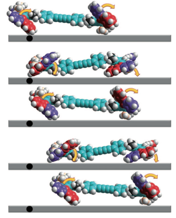
The coordinates were in fact quite difficult to acquire (from the journal), but are presented her for your enjoyment, together with thoughts of how the motor might work!
Preparing the Coordinates: Crystallographic coordinates relate to what is called a unique unit cell, and not necessarily to a discrete entity we call a "molecule". If one is lucky, the unit cell will contain at least one "molecule", but it may also contain fragments of molecules which span the cell. In creating a set of coordinates suitable for visualisation, one may have to multiply one or more of the x, y or z boundaries of the unit cell by e.g. a factor of 2 (or even more) to recover particular effects, such as intermolecular hydrogen bonding, molecular stacking, etc. A good program for doing this sort of operation is Mercury, from the CCDC centre. If you want to go one step further and actually change the structure and re-optimise the coordinates, you will have to worry about atom hybridisation (next section).
Pros: Needs no (expensive) software, data often available from databases, interpretation uses simple "arrow pushing" concepts, fast.
Cons: Recording structure can be slow (2 days per structure), need to "normalise" result, not quantitative, ie can be difficult to relate geometric features to measurable quantities such as the relationship between a bond length and the rate of hydrolysis, no modifications can be made to the original structure.
Back to scales|Forward to Mechanics| Forward to MO Reactant|Forward to MO TS| Forward to MO Advanced|
(c) H. S. Rzepa 1998-2013. No reproduction rights granted to this material without permission.