5.1 Magnetism
So far we have discussed the forces between charges which are at rest with respect to each other. When charges are moving relative to each other they exert an additional force, the magnetic force. This force, as we will see later, plays a negligible role in inter atomic and intermolecular bonding. However, the effect of magnetic fields on atoms and molecules is used widely in all manner of spectroscopies, and we will need to appreciate magnetic behaviour in order to understand the interaction of light and other electromagnetic radiation with atoms and molecules.
5.1.1 The Lorentz Force
Magnetic materials were discovered well before the electrostatic effects of rubbing amber. The magnetic iron oxide, magnetite, was mined in Asia Minor well before the birth of Christ, indeed by about 100 BC the Chinese had already discovered that such minerals would align with the north and south poles. By the beginning of the 19th Century it was known that such bar magnets would repel if like poles were facing each other and attract if the poles were of the opposite sense, and the similarities with the behaviour of electric charges had for some time interested scientists of the time.
In 1820 the Danish scientist Hans Christian Oersted performed a sequence of experiments which demonstrated that moving charge exerted a force on a permanent magnet. In the same year Ampère showed that as Newton's third law predicted, the opposite was also true, that a magnet exerted a force on a moving charge.
They made the following observations
* the force is proportional to the magnitude and sign of the charge on the particle
* the force is proportional to the velocity of the charged particle
* the force is proportional to the magnitude of the magnetic field
* the magnitude of the force depends on the relative orientation between the line of flight and the direction of the magnetic field
* and the force always acts perpendicularly to the particle's line of flight.
The last statement is the least expected, since so far we have only met forces which act in the same direction as the field. Mathematically the only way in which multiplying two vector quantities, in this case the velocity and the field, results in a vector which is mutually perpendicular, the force, is to apply the vector cross product.
F = qv x B (5.1.1)
where B is the magnetic field (the unit of magnetic field is the Tesla (T)). You should note that the field direction has been set by the requirement that F is perpendicular to v. However, it ensures that if we use a compass needle to map out the field the north pole will point in the direction of the magnetic field.
This force, is called the Lorentz force. (Lorentz was the Dutch physicist whose relativistic co-ordinate transformations were used by Einstein in his theory of special relativity. The rules of special relativity demonstrate that the magnetic force is in fact just the electrostatic force under a relativistic transformation. This interesting fact will not concern us here.)
The magnitude of the force is given by
F = Bqv sinθ (5.1.2).
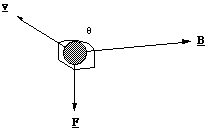
The quantity θ is the angle between the magnetic field and the particle's direction of travel. So if a charge travelling in the region of a magnetic field experiences no force, we would say that by definition it is travelling parallel to a field line. The maximal force is exerted when it flies perpendicular to the field.
It is easiest to see the direction of this force in a drawing.

Figure 5.1.1. The Lorentz force on a positively charged ion.
One way to remember the relative direction of the force is by imagining the direction a right handed screw would move if it were turned through the angle θ from v to B.
5.1.2 The Mass Spectrometer
The classic use of the Lorentz force in the Chemistry Laboratory is with the mass spectrometer, figure 5.1.2.
Here an unknown molecule in the vapour phase is ionised (and dissociated) by being bombarded with high energy electrons. Some of the ion fragments emerge via a small aperture into a region of uniform electric field between two parallel flat plate conductors with a large potential difference between them. Here they are accelerated to form a beam of ions which emerge through the second aperture, after which they pass through a region of uniform magnetic field at right angles to their line of flight, before being detected.
We will first deal with the acceleration of the ionised fragments. If a voltage, V, is imposed across the conducting plates the potential energy of a singly ionised fragment, charge e, as it enters the field filled region is eV. The kinetic energy at this point is essentially zero. On emerging through the second aperture there is no longer any significant electric field and therefore the final kinetic energy must be eV. Hence the speed of the emerging ion is
 (5.1.3),
where m is the fragment's mass.
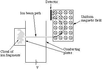
Figure 5.1.1. The mass spectrometer. The B field is represented by a circle with a cross in the centre to show that the field is in to the page, i.e. an arrow viewed from the back.
The particle now enters the region of uniform magnetic field. Since B and v are mutually perpendicular the magnitude of the force on the ion is
 (5.1.4).
The B field is shown going in to the page and hence the force acts in the direction shown in figure 5.1.2. Since the force is always at right angles to v and B the particle must follow a circular path. This means the Lorentz force is equal to the particle's mass times the centripetal acceleration and substituting for the speed we get
 (5.1.5).
Hence the radius of the path taken by the ionised fragment is
 (5.1.6).
So by recording the number of ionised fragments as a function of distance r in the detector plane we can measure the mass directly.
5.1.3 Magnetic Field and Field Lines
To determine the magnetic force on an ionised atom or molecule the magnetic field must be known. Determining the magnetic field is a non-trivial exercise which we will omit (except for the brave, see [[section]]5.1.4). Instead we will see what the magnetic field lines for charge travelling in a line and in a circle will look like.
The most striking characteristic of the magnetic field lines for a straight line of current is that the field lines are continuous, figure 5.1.2. That is, unlike electrostatic field lines, they do not originate from one location and end at another. This continuity of the field lines is always true of the magnetic field. In order to be consistent with our definition of the field in the Lorentz force we define the direction of the field lines by the right hand screw rule.
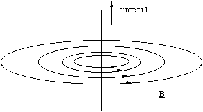
Figure 5.1.2. The magnetic field around a straight current carrier.
You can remember the right hand rule by pointing the thumb of your right hand in the direction of the current and making a fist of the rest of your fingers. The direction in which your fingers point indicate the field direction. The only other thing you need to remember is that the current is defined as moving in the direction that positive charge travels!
The field pattern for a current loop can be sketched by remembering that the lines are continuous and they circulate around the conductor, figure 5.1.3. The field pattern has obvious similarities to the electrostatic dipole and is called, by analogy, the magnetic dipole. Clearly an electron circulating around the nucleus would constitute a current loop and as such we would expect it to produce a magnetic dipole field. In fact not only does the atom possess a magnetic dipole field, but so do electrons and protons. The magnetic dipole from these cannot be described classically, they are an intrinsic quantum mechanical property. However, the ways in which these magnetic dipoles interact with each other and external fields is important in the interpretation of the spectroscopic behaviour of atoms and molecules.
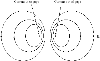
Figure 5.1.3. The magnetic dipole. The current loop is coming out of the page and has been cut in half.
5.1.4 Determining the Magnetic Field
We now turn to the determination of the magnetic field using the Biot-Savart law. This is the magnetic equivalent of the superposition principle, but its appearance is far more daunting!
The Biot-Savart law expresses the magnetic field as the sum of tiny sections of a current carrying circuit.
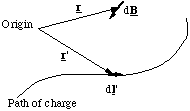
Figure 5.1.4. The Biot-Savart construction.
The contribution to the magnetic field at the point defined by position vector r from the circuit element dl' (which points in the direction of current flow) is given by
 (5.1.7),
where I is the current, r - r' is the vector pointing from the circuit element to the location where the field is being calculated and μ0 is a universal constant, the permeability of free space, which is 4πx10-7 kg.m.C-2 exactly. The current is defined as the flow of charge per unit time in the circuit and has units of Ampères ( 1A = 1 Coulomb per second).
To see how one uses this equation we will look at the calculation of the magnetic dipole field along the axis of a current loop.
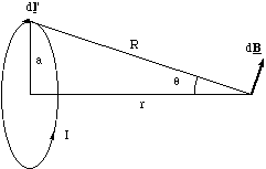
Figure 5.1.5. The construction for calculating the axial dipole field.
We place the origin at the centre of the loop and let r - r' = R for simplicity, figure 5.1.5. The field contribution from dl' is perpendicular to R and faces radially outwards from the axis for the current circulation shown. This means that if we sum up all elements dl', the field component perpendicular to the axis must, by symmetry, be zero. The field will only add up along the axis. The axial contribution, dBaxis, from our element is
 (5.1.8),
where we omit vector notation for the moment. Summing up all elements, we see that all the quantities are independent of dl', so we get
 (5.1.9).
The total length of the current loop is of course 2πa, and expressing R and sinα in terms of a and r we get the magnetic field along the dipole axis.
 (5.1.10),
where the unit vector is shown on the figure and can be determined by the right hand screw rule.
When r2>>a2 we can approximate the denominator, as we have done previously, to get
 (5.1.11),
where m is the magnetic dipole moment, in analogy with the electrostatic case, and is equal to Iπa2n, i.e. the magnitude of the dipole moment is given by the area circumscribed by the loop times the current.
Using similar methods it is possible to show that the magnitude of the axially symmetric, tangential field around a straight conductor is given by
 (5.1.12),
where r is the perpendicular distance measured from the conductor.
5.1.5 Torque on a Magnetic Dipole - Precessional Motion
We have calculated the torque on an electrostatic dipole due to an electric field, so let's now calculate the torque on a magnetic dipole due to an external magnetic field.
To simplify the problem (but without losing generality) we will model the dipole as a current circulating around a square path rather than a circular one, figure 5.1.6.
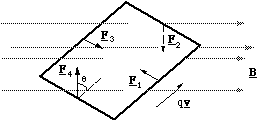
Figure 5.1.6. The torque on the magnetic dipole. The subscripts on the force vector refer to the number of each edge.
The dipole is placed in a uniform field so that edges 2 and 4 are perpendicular to the field lines and 1 and 3 are oriented at an angle φ (not shown on figure). The positive charge q, circulating around the square with speed v will experience a Lorentz force of magnitude Bqv on edges 2 and 4 and Bqvsinφ on 1 and 3. The direction of the force on edges 1 and 3 is equal and opposite and produces no torque. The direction of the forces on edges 2 and 4 are also equal and opposite, but here there is a torque given by
 (5.1.13),
where l is the length of each edge and Τ is the total torque on the dipole. Now the current, I, circulating around the dipole (units of charge per unit time) is equal to qv/l. Hence we can re cast the expression for the total torque
 (5.1.14).
Now Il2 is the current times the area circumscribed by the circulating current and in analogy with the electrostatic dipole moment this is called the magnetic dipole moment m. The dipole moment vector is perpendicular to the plane defined by the circulating current and its direction is given by the right hand screw rule. The vectorial version of (5.1.14) is therefore
 (5.1.15).
We now go on to consider what happens to a molecule, which has both angular momentum, i.e. the molecule is rotating, and a magnetic moment, i.e. circulating electrons. L and m need not be pointing in the same direction, so we will consider two cases; L and m mutually perpendicular to each other and B, figure 5.1.7, and L and m parallel, but perpendicular to B, figure 5.1.8.
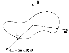
Figure 5.1.7. In this example the applied torque (m x B) is in the same direction as L and hence the change in angular momentum in the time dt is (m x B) dt.
In figure 5.1.7 we can see that the torque resulting from the interaction between the dipole and magnetic field increases the magnitude of the angular momentum, but does not change its direction. (If the magnetic field were to point in the opposite direction it would of course reduce the angular momentum.)
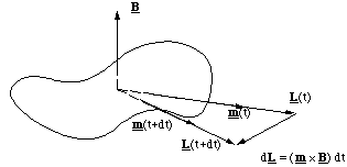
Figure 5.1.8. In this case the torque is perpendicular to L and the molecule is made to precess.
When L, m are parallel but perpendicular to B something rather unexpected happens. Now the torque is at right angles to L and since T = dL/dt it is clear that the change in L after a short interval dt is Tdt. This is a vector pointing perpendicular to L in this case and therefore does not change the magnitude of L but does change its direction. In other words, since L and m are fixed in relation to the molecule, the molecule turns around in a circle (much more slowly than the spinning along L) perpendicular to B. This motion is called precession.
The precession of spinning molecules which have magnetic moment when they are placed in a magnetic field is a general phenomenon. The rate of the precession depends on the neighbouring chemical environment and can be probed electromagnetically. You will use this effect every time you examine a compound using nuclear magnetic resonance.
5.2 The Origin of Electromagnetic Waves
We are now in a position which will allow us, at least qualitatively, to describe the origins of electromagnetic radiation and its interaction with atoms and molecules. The description given here largely follows that given by Blatt.
We already know what the dipole field looks like. If we were to measure the field at the point P, a long distance away from the dipole, we would find the field pointing in the negative z direction.
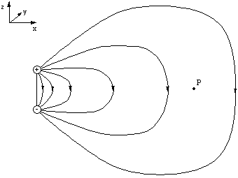
Figure 5.2.1. The electric field at t=0.
Let this first measurement be made at time t=0. If the charges execute simple harmonic motion and become inverted at a time t = T/2 and we measure the field at P again the field has the same magnitude but now points in the positive y direction. We would therefore guess that E would vary sinusoidally at P.
The question is, does this sinusoidal variation in E occur at the same instant as the sinusoidal variation in the atomic positions? Maxwell found that in fact the variation in E takes time to propagate through space. The speed at which it does this is given by
 (5.2.1),
which is the speed of light, normally denoted c. So changes in the field propagate at the speed of light! We will use this fact to sketch the electric and magnetic field variations for our dipole oscillator.
We imagine that we have stopped the oscillation after one half cycle, i.e. at t = T/2, and measure the electric field pattern at t = T. At a distance r < cT/2 and a distance r > cT the field lines are strictly dipolar, but with the field directions inverted. In the portion of space in between cT/2 and cT the field lines can be determined by remembering that in a region which is free of charges the lines must either be continuous or extend to infinity. The only way to accomplish this is in the way shown below.
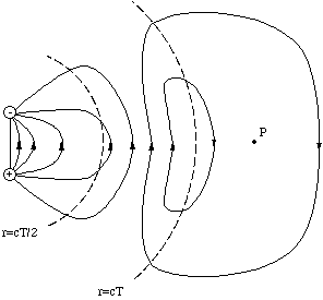
Figure 5.2.2. The electric field after half a period of dipole oscillation.
Hence if we allow the dipole to execute simple harmonic motion the electric field variation at P would correspond to
E = E0sin(kx - ωt) (5.2.2),
where E0 is the amplitude at t=0 at position P, and in this case points in the z - direction, ω is the oscillation frequency of the dipole and k is called the wave number and is given by
 (5.2.3),
where λ is the wavelength of the undulations in the electric field.
The moving dipole charges of course also constitute a source of magnetic field. Here the direction of motion of the positive charge and negative charge are in opposite direction, but since the sign of the charges is opposite the current produced will point in the same direction.
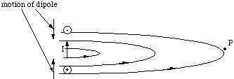
Figure 5.2.3. The magnetic field from the oscillating dipole is equivalent to the field from a straight conductor.
By the right hand rule, it is clear that the magnetic field lines at the point P are perpendicular to the electric field at all times, i.e. they lie in the x-y plane and point in the y-direction. We cannot take our simplified picture of the electromagnetic wave too far at this point. It would predict that the magnetic and electric field were out of phase, whereas they are actually in phase. This error is due to the fact that we have only learned how to determine the magnetic field which is static, when it varies an added complication occurs. The complete theory predicts that the resultant electromagnetic wave at P travels in the x direction and has transverse oscillations in the z direction of the electric field and in the y direction of the magnetic field and that these are in phase.
 (5.2.4).
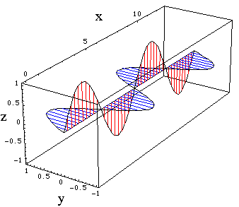
Figure 5.2.4. The electromagnetic wave. E oscillates in the z direction B in the y direction. (For code see "Physical Chemistry: Molecular Interactions: Electromagnetic Wave.)
From what we have already seen about the torque created by electric and magnetic fields on dipoles, we would expect that the electromagnetic wave would cause molecules to rotate and precess. Additionally an electrostatic dipole lined up along the z direction in our example would be forced to oscillate. These effects are remarkable, because the conservation of energy tells us that we can transfer vibrational energy across empty space in the form of electromagnetic waves, and thereby induce other dipoles to oscillate or to rotate.