 (4.1.1).
4.1 Measuring Rotational Motion
So far we have looked at the linear and vibrational motion of molecules. we will now turn to the third form of molecular dynamics, which is to be found in rotational motion. This is far and away the most difficult form of motion to analyse, so we will only examine it in a restricted form, that of rigid body rotating about a fixed axis. For such a system the atoms making up the molecule follow circular trajectories in a plane perpendicular to the rotational axis. In other words every atom will rotate in the plane, i.e. it exhibits two dimensional rotational motion.
As was pointed out at the beginning of this course, in the absence of any external forces the axis of rotation must pass through the centre of mass. What we will do now is to derive the centre of mass precisely.
4.1.1The Centre of Mass
Imagine a molecule consisting of j atoms, each of which has a force Fj acting on it. The subscript j simply identifies the atom under consideration. This force is of course equal to the atom's mass, mj, times the acceleration it experiences, d2rj/dt2.
 (4.1.1).
The total force, F, on the molecule is then the vector sum of these individual forces.
 (4.1.2).
Now F is equal to the total external force on the molecule, since Newton's third law tells us that all the forces exerted by atoms within the molecule on each other must cancel out; equal and opposite reactions. This then only leaves the forces exerted on the atoms by external sources.
Now if we symbolise the molecule's mass by M, we can re-express our equation for the total external force on the molecule by
 (4.1.3)
were R is the position vector of the point through which the external forces effectively act, the centre of mass. The position of the centre of mass is therefore given by
 (4.1.4).
We are now in a position to be more specific about the utility of the centre of mass. First, in the absence of any external forces Newton's first law tells us that this point must be moving with constant velocity dR/dt. Now the molecule may well be rotating under these conditions (an external agent must set the rotation in train, but need not be present for the rotation to continue). In such a case it is clear that this rotation must have the centre of mass on the axis of rotation, since otherwise dR/dt will not be constant. Indeed any internal motion in the absence of external forces must have the centre of mass at this "still" point.
The corollary of all this is that if we use the centre of mass as the origin for all our measurements of internal motion, such as rotational motion, we can ignore the motion of the centre of mass itself. Indeed we have already used this trick in our examination of SHM in a diatomic molecule.
4.1.2 Rotational Kinematics
As with linear motion we must develop the kinematic equations for circular motion in order to be able to describe the dynamics of rotation. To do this it is obviously not sensible to use the rectilinear co-ordinates x, y, z, figure 4.1.1.
Since the rotation is about a fixed axis the co-ordinates r and θ will enable us to specify a particle's angular kinematics. Since we will only consider a rigid body only the angle θ will vary with time. This means we need only measure the rate of angular rotation, ω
 (4.1.5)
and the rate of change of angular rotation, α
 (4.1.6)
in order to describe the kinematics of such systems. If we measure θ in radians then ω, the analogue of velocity, has units of radians per second and α, the analogue of acceleration, has units of radians per second squared.
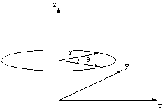
Figure 4.1.1. Cylindrical co-ordinate system.
This analogue between one dimensional linear kinematics and angular kinematics, i.e. that θ corresponds to x, ω corresponds to v and α corresponds to a, makes it extremely easy to write down the kinematic equation for motion under constant angular acceleration.
 (4.1.7)
where the subscript zero indicates the value of the appropriate quantity has been measured at t = 0.
Of course θ, ω and α are actually vectors since they must be able to indicate the direction of the rotational motion. The sensible place to put the vectors θ, ω and α is on the axis of rotation. Having done this the only remaining decision to be made is in which direction the vectors should point. By convention we use the right hand screw rule to determine the direction in which the vectors point, figure 4.1.2.
In the figure the direction of θ and ω have been determined as follows. The particle is rotating anti-clockwise, if we were to turn a right handed screw in the same sense it would travel in the positive z direction. This is the direction in which the vectors must therefore point by the right hand screw rule. We show α pointing in the opposite direction, which means that the particle's angular velocity is slowing down.
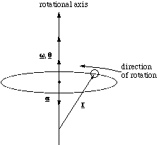
Figure 4.1.2. Determining the direction of rotation vectors.
In calculations we will want to be able to relate the angular velocity and acceleration to the instantaneous linear velocity and acceleration of a particle, figure 4.1.3.
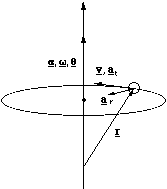
Figure 4.1.3. Relating angular and linear kinematic quantities.
The derivation of the relationships between v, at, ar and ω and α is given in [[section]]4.1.3, we simply quote the results here and explain their meaning. The instantaneous velocity is given by
 (4.1.8).
The order of the vector cross product multiplication, ensures that v points in the correct direction. Remember that the magnitude of v = ωrsinθ, where θ is the angle between the vectors ω and r. This means that v is simply ω times the perpendicular distance from the axis of rotation to the particle. So even though it make sense to put the origin for the position vector at the centre of mass, for the purposes of these calculations, it suffices to ensure that the origin is somewhere along the axis of rotation.
The radial and tangential accelerations are given by
 (4.1.9).
Once again the magnitude of the tangential acceleration is equal to α times the perpendicular distance from the rotation axis to the particle and the radial or centripetal (in towards the centre) acceleration is equal to ω2 times the perpendicular distance from the axis of rotation to the particle. More importantly, even if the rate of rotation is constant there is still a radial or centripetal acceleration. This must be so, because we are forcing the particle to deviate from a straight path, which according to Newton's first law can only be done by applying a force and hence imparting an acceleration.
4.1.3 Relating Angular and Linear Velocity and Acceleration.
In order to examine the dynamics of rotational motion in a molecule we need to determine the instantaneous acceleration and velocity of the constituent atoms. We find the appropriate relations in the following manner.
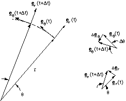
Figure 4.1.4. Radial and transverse components in a rotating system.
Figure 4.1.4 shows a particle rotating in a circular path about the z axis in the x-y plane at a constant radius r. We define two units vectors er and eθ pointing in the radial and transverse or tangential directions. So the rectilinear position vector, r, is given by
r = er r (4.1.10)
and hence the instantaneous velocity of, v, is given by
 (4.1.11).
Now looking at our vector diagram we can see that to convert this into an angular velocity ω, we can take advantage of the fact that
Δer =Δθ (4.1.12),
where we define angles in radians, and the angle is small enough, which it will be for an instantaneous measurement. Now examination of the vector diagram should convince you that this change in the radial vector actually points along the transverse direction and hence we get
 (4.1.13)
and hence
v = eθ ωr (4.1.14).
To find an expression for the acceleration we simply differentiate this expression
 (4.1.15),
but dω/dt is simply the angular acceleration α and you can show, in the same way that we previously did for der/dt that
 (4.1.16),
which gives us
a = eθ αr - er ω2r (4.1.17).
This shows us that the acceleration has a tangential and radial component. The tangential acceleration at is simply proportional to the angular acceleration. However, even if α is zero there is a radial acceleration ar, directed towards the axis of rotation (the negative sign). The acceleration is called the centripetal acceleration and is present even at constant angular velocity, because we have to apply a force in order to make a particle deviate from straight line motion (Newton's first law). In the case of circular motion at constant angular velocity, the instantaneous rectilinear velocity is changing in direction, but not magnitude.
We have yet to express the angular kinematic terms as vectors, which we will need to do in order to understand forces and momenta in rotating systems, since these are of course vectorial. Let us deal with the instantaneous velocity and angular velocity first.
The magnitude of the velocity is given by
v = ωr (4.1.18).
Since v and r are vectors and ω should also be a vector we can see that the only appropriate combination is the vector cross product, the only remaining ambiguity being the order of the multiplication. By convention the right hand rule is used, giving us
v = ωxr (4.1.19).
Remember that this makes the magnitude of v times the sine of the angle between the vectors w and r. This means that the magnitude of the velocity is equal to the angular velocity times the radial distance between the axis of rotation and the moving particle. The radial and tangential acceleration then follow
at = α xr (4.1.20)
ar = ω x v (4.1.21).
4.2 Torque and Angular Momentum
We now have kinematic equations for rotational motion, so we are equipped to look at the dynamics of rotation. What we will find is that there are direct parallels between the equations of linear dynamics and those for rotational dynamics. This is not a great surprise, since rotational dynamics is in fact only a re-expression of linear dynamics in a rotating frame. Those analogues are summarised below.
Linear Dynamics Rotational Dynamics
v / ω
a / α
m / I
F = ma / τ = Iα
p = mv / L = Iω
dWlin = F * ds / dWrot = τ * dθ
Klin = 1/2 mv2 / Krot = 1/2 Iω2.
Let us start by looking at the rotational analogue of force, the torque (from torquere, the Latin for twist).
4.2.1 Defining the Torque and the Moment of Inertia
Everyday experience tells us that the action which causes an extended object to rotate depends both on the magnitude of the applied force and the distance from the axis of rotation. If you want to push open a door, you apply the force at the edge of the door furthest from the hinge. In this way you maximise the turning effectiveness of your push or pull. If you try opening the door by applying a force close to the hinge you will find the effort required is far greater. Clearer the further away you are from the axis of rotation the greater the effect of a given force. So we would guess that the torque, τ, is related to the force, F, by
τ = rF (4.2.1),
where r is the perpendicular distance from the axis of rotation to the point at which the force was applied.
So far we have not determined the vectorial nature of the torque. We can determine this when we note that only the component of force acting tangential, Ft, to the direction of rotation is used to cause the rotation, figure 4.2.1. Returning to the example of a door, this is simply saying that if you apply the force along the door face you will not make it turn at all, whereas if you apply the force at right angles to the door face you maximise the efficiency with which you turn it.
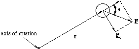
Figure 4.2.1. Only the component of the force perpendicular to r, Ft is used in turning the particle about the axis of rotation.
This means we would now conclude that
τ = rF sinθ (4.2.2),
where θ is the angle between the position vector and the force vector, figure 4.2.1. Putting this into vectorial language
τ = rxF (4.2.3)
and the vectorial construction once again follows the right hand rule. Of course in a molecular calculation the total torque, Τ, is the sum of the torque on each atom
 (4.2.4),
where the subscript j identifies the jth atom. Clearly the value of the torque will in general depend on the location we choose as the origin of our co-ordinate system. It is best therefore to choose the centre of mass as the origin for our measurements, although it is well to note that in conditions where the net force on the molecule is zero, i.e. in conditions where the external forces only cause rotational motion, the value of the total torque is equivalent from whatever point the measurements are made.
Since we now have the rotational analogue of the force, we will derive the equation which would be analogous to F = ma. Consider the case of a torque applied to a mass, m, at a distance r from the axis of rotation, where θ = π/2.
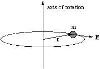
Figure 4.2.2. Deriving the moment of inertia.
In this case the magnitude of the torque is
τ = rF (4.2.5),
but the applied force, F, is equal to the particle's mass times the tangential acceleration (since r is constant). Therefore
τ = rmat (4.2.6),
but at = αr and therefore
τ = mr2α (4.2.7).
Now mr2 is called the moment of inertia, I, which is the rotational analogue of the inertial mass in linear motion. In other words the larger the moment of inertia the harder it is to get the object to change its angular velocity. In full vectorial form we have
τ = I α (4.2.8)
and if you check you can see that this expression is consistent with the direction of vector cross product r x F .
In all the cases of interest to us there will be more than one mass to consider in calculations of the effect of a torque applied to a molecule, so we must generalise the moment of inertia for a system of connected masses (atoms)
 (4.2.9),
where rj is the perpendicular distance of the jth atom to the axis of rotation.
4.2.2 Turning a Molecule - The Dipole in an Electrostatic Field
A dipolar molecule in the presence of an electrostatic field will, in general, experience a torque. We will calculate this torque for a diatomic dipolar molecule in a uniform electrostatic field, figure 4.2.3.
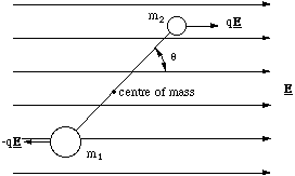
Figure 4.2.3. An electrostatic dipole in a uniform electric field. The distance between the dipole charges is 2l.
There is no net force on the dipole, but there is a torque. We will determine the torque exerted by the field on each charge, measured about the centre of mass, using the fact that the magnitude of the torque is given by the product of the distance to the charge and the tangential force. The distance to the centre of mass is given by (2.1.1) and hence we find the total torque Τ to be
 (4.2.10).
The torque vector is into the paper, since the turning action is clockwise and a right handed screw would travel in this direction. Noting that cos(π/2-θ) = sinθ, (4.2.10) reduces to
 (4.2.11)
and we note that 2lq is the magnitude of the dipole moment, which suggests that the torque is the vector product of P and the field E. The appropriate order of vector product is
 (4.2.12)
and indeed this is always the torque on an electrostatic dipole in a uniform electric field.
The torque on the dipole depends on sinθ. This means that the force is zero at θ = 0 and π, i.e. the dipole is in equilibrium with P parallel and anti-parallel to E. The difference in these two positions, is that only the parallel state is in stable equilibrium.
4.2.3 Defining the Angular Momentum
We now derive the most important rotational quantity in dynamics, the angular momentum, L, the analogue of linear momentum. Now we already know that F = dp/dt so we should have exactly such a correspondence between the torque and the angular momentum, i.e.
 (4.2.13).
This expresses the fact that the total angular momentum of a molecule (found by summing the individual momenta of the constituent atoms) is constant unless an external torque is applied. In other words we have identified an important conservation law, that in the absence of any external torques, the angular momentum of an isolated system is always conserved. Put into mathematical terms
 (4.2.14),
where Lij is the initial angular momentum of the jth atom and Lfj is the final momentum of the jth atom.
Since the torque τ = r x F we anticipate that L = r x p. We can check this by re-expressing τ = dL/dt as
 (4.2.15)
and we can confirm the validity of our expression relating torque and angular momentum by doing the differentiation
 (4.2.16)
and noting that v x v must be zero, which returns us to the original expression and confirms that the angular momentum is given by
L = r x p (4.2.17).
Now we can derive the analogue of p = mv, which we anticipate will be L = Iω, for the angular momentum. For simplicity, but without loss of generality, we set r in the rotational plane of the particle. Recalling that v = ω x r and substituting into our expression for L, we get L = r x (mω x r). This has a magnitude mr2ω and inspection of the vector diagram, figure 4.2.4, shows that the resultant vector points in the same direction as ω, hence
L = Iω (4.2.18).
So we now see that, as we would have expected, the analogy between linear momentum p = mv, and angular momentum is exact ( with I and ω replacing m and v).
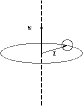
Figure 4.2.4. The vectorial construction used to determine l = Iω.
4.2.4 Dipole Oscillations
We have seen how a diatomic molecule stretched along its long axis will oscillate. We now show that a dipolar molecule in the presence of an electric field may also execute rotational oscillations.
We return to the example given in [[section]]4.2.2 and note that in order to perturb the dipole away from the stable equilibrium position at θ = 0 we would have to apply a torque, τa, equal but opposite to the torque due to the field
 (4.2.19).
According to (4.2.13) this applied torque is equal to the rate of change in angular momentum, L. Since the bond length does not change, neither can the moment of inertia I, so dL/dt = I dω/dt = I d2θ/dt2 and hence we have
 (4.2.20),
where I have removed the vector notation since α and θ point along the same axis. When the perturbation is small sinθ ~ θ and hence we have
 (4.2.21)
which is a very simple second order differential equation, the solution of which is θ = θ0sin(ωt+φ), where ω = [[radical]](PE/I) and θ0 is the angular amplitude. In other words we have simple harmonic oscillations whose period does not depend on the amplitude θ0.
4.3 Rotational Energetics
4.3.1 Rotational Work, Potential and Kinetic Energy
Finally we will look at the energetics involved in rotating a molecule. Continuing our analogies to linear dynamics, the work done in rotating a molecule through an angle dθ by the action of an external torque will be given by
dWrot =τ *dθ (4.3.1),
which is directly analogues to the definition of work for a linear displacement, with the force being replaced by torque and linear displacement being replaced by angular displacement.
By extension we may then also deduce that the potential energy associated with rotating the molecule is given by
dUrot = -τ *dθ (4.3.2).
The kinetic energy of a particle of mass m moving in a straight line is 1/2 mv2. If the particle moves in a circle we know that v = ωr and hence we would expect the rotational kinetic energy to be
Krot = 1/2 mω2r2 = 1/2 Iω2 (4.3.3)
and once again the moment of inertia replaces the inertial mass and ω replaces v.
We now have the means to solve dynamical problems in rotation using the conservation of energy and the conservation of angular momentum.
4.3.4 Energy of the Oscillating Dipole
Let us return to the case of a dipole in a uniform electric field [[section]]4.2.2 and determine the energetics of the small rotational oscillations. We first determine the potential energy of the dipole at an angle θ away from stable equilibrium. A torque would be needed to hold the dipole at the angle θ which was equal and opposite to the torque produced by the field, i.e. the holding torque would be -PEsinθ. Hence the potential energy is given by
 (4.3.4).
For small perturbations from equilibrium sinθ ~ θ. Using this approximation in the integral gives the following relationship
 (4.3.5).
The total energy of the system will include the kinetic energy, 1/2 Iω2. Hence the total energy H is given by
 (4.3.6)
which has exactly the same mathematical form as the total energy of the simple harmonic oscillator (see equation (3.1.11)). So as we have already seen in [[section]] 4.2.4, the dipole will execute simple harmonic oscillations with period T = 2π [[radical]](I/PE).
4.3.2 The Oscillating and Rotating Diatomic Molecule
In general molecules will have translational, vibrational and rotational motion. Since the translational motion can be de coupled from the internal ones, we will now examine a simple case of a homonuclear, diatomic molecule which is both rotating and vibrating. To simplify the problem we have the molecule rotating orthogonally to its molecular axis and vibrating along it, figure 4.3.1.
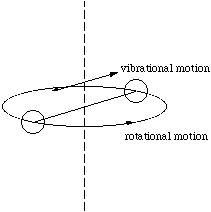
Figure 4.3.1. The rotating and vibrating diatomic molecule.
No external forces are applied during the vibrational movement of the atoms from the radial distance r1 to r2. Therefore the initial and final angular momenta, L1 and L2 respectively, must be equal. However, changing the radial separation of the atoms alters the moment of inertia. Hence according to the relationship L = Iω, ω must alter, from ω1 to ω2 to preserve the value of L. For atoms of equal mass, m we then have
 (4.3.7)
which re-arranges to give
 (4.3.8)
where we have omitted the vectorial notation, since the direction of rotation does not alter. Clearly since r1>r2, we have that ω2>ω1. In other words as the atoms come closer together the rotation rate speeds up and as they part company the rotation rate slows down.
It is interesting to note that although the angular momentum is conserved, we can show that the rotational kinetic energy, K, is not.
 (4.3.9),
where K2 is the kinetic energy at position r2 and K1 is that at r1. We simplify this expression by noting that since the angular momentum is conserved we may substitute for ω2 by L/2mr2, to give
 (4.3.10)
which is true for r1
 r2.
r2.
This is actually not too mystifying when you think about it, since moving the atoms inwards takes work. In other words the total energy is conserved, we have just forgotten to take into account the change in potential energy.
The work can be found as follows. An inward radial force, magnitude F, must be exerted to keep the atoms moving in a circular path. This force is equal to the centripetal acceleration times the mass of the atom. For one atom
F = mω2r (4.3.11).
Now as the atoms are pulled in the force and displacement are in the same direction and so the work done on one atom is simply
 (4.3.12),
but ω varies with r so we will substitute for ω again using the invariant L= 2mr2ω (in our case). The potential energy change is the negative of the work and remembering that there are two atoms we get
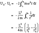 (4.3.13).
So we now have (U2 - U1) + (K2 - K1) = 0 as required!
The diatomic molecule will clearly change its rate of rotation exactly in time with the natural frequency of the vibrational oscillations. The motions are coupled.