The Imperial College 2D-IR group have 2 ultra-fast laser systems for 2D-IR.
Our labs are actively temperature stabilised to within 0.5 of a degree C.
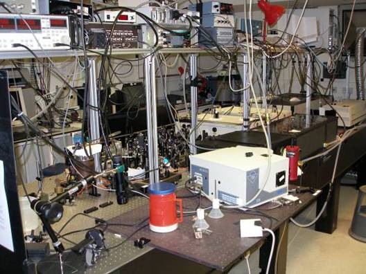
Quadrant 1 2D-IR System
Spectra Physics Spitfire system: 1 W, 1 ps/pulse at 1 kHz and 790 nm. Two OPAs 800C-P provide tunable light from the UV to the IR.
To acquire 2D IR spectra, two IR beams (ωα and ωβ) and a visible beam (ωγ) are non-collinearly overlapped in time and space on the sample. Figure 6b shows the optical layout for this experiment. The FWM signal at ωδ=ωγ+ωβ-ωα is detected in the visible with a photomultiplier while the infrared beams wavelengths are scanned over the spectral region of interest. The laser used is a commercial system comprising a femtosecond oscillator and a picosecond regenerative amplifier. The amplifier delivers 1 ps pulses at 790 nm and 1 kHz with approximately 800 uJ/pulse. This beam is split into three parts. Two of them pump two picosecond IR Optical Parametric Amplifiers (OPA) which deliver the two tunable infrared beams. The orientations of the crystals and gratings in the OPAs are controlled with actuators and the scan is made by a computer-controlled procedure. The visible beam wavelength is 790 nm (12658 cm-1). All three beams are horizontally polarized, and the unpolarized FWM signal is detected. The FWM signal is recorded whilst scanning ωβ for each ωα frequency. The data obtained are two-dimensional maps of the FWM signal level as a function of ωα and ωβ. All three beams are initially spatially overlapped through a 100 um pinhole at the sample position, and the overlap in time is found first for the visible and ωβ beams by sum frequency generation in a BBO (β-Barium Borate, β-BaB2O4) crystal. Then the time overlap with ωα is found by detecting non-resonant four-wave mixing signal in a CaF2 window placed at the sample position.
The following schematic descibes the optical paths of the three beams (ωα and ωβ are IR and ωγ visible) and the optical elements used for the 2D-IR experiment:
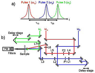
a) Time sequence of the three pulses used in the experiment. The delay between the first pulse (frequency ωα) and the second pulse (frequency ωβ) is denoted t12, the third pulse arrives with a delay t23 after the second pulse.
b) Optical setup for 2D IR FWM experiment. The lenses (L1 to 7) are all CaF2 lenses. For both telescopes on the ωα and ωβ beam paths, the focal lengths for L1 and L4 are 5 cm and for L2 and L5, 15 cm. Both IR beams are spatially filtered with 100 microns pinholes placed at the focal points of the beams in the telescope. The focusing lenses L3 and L7 both have a focal length of 20 cm; L6 is a 10 cm focal length lens. The ωβ IR beam is approximately at normal incidence on the sample. The visible beam and the IR beam at ωα have angles of incidence relative to the ωβ IR beam of around -2 degrees and 8 degrees respectively. These angles are calculated to have the optimum phase matching for the FWM process. The FWM signal is detected with a photomultiplier after going through a series of filters (three short pass filters at 770 nm and a 40 nm bandwidth interference filter at 700 nm).
The time delays of the ωβ IR pulse and visible pulse relative to the ωα IR pulse are controlled by two delay stages. It appears that the spectral scanning of the OPAs significantly changes the optical path length of both IR beams and thus the time delays between the pulses. We measured a time difference of approximately 3 ps when ωα is scanned from 1300 cm-1 to 1700 cm-1. To keep t12 and t23 constant inside the spectral range scanned, we implemented a computer-controlled procedure which scans the delay stages during the IR spectral scans.

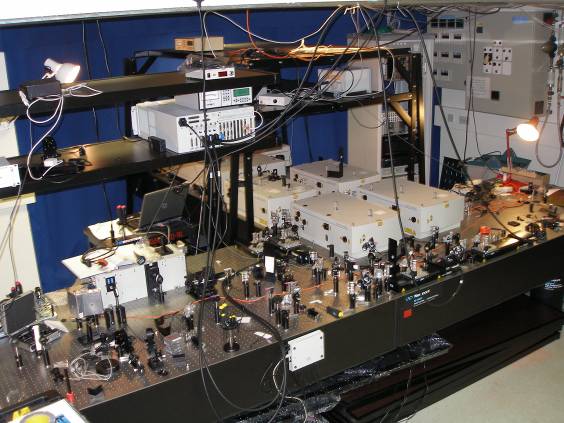
Quadrant 4 SCP 2D-IR System
(under construction)
Spectra Physics Spitfire XP Pro system: 3 W, 1 ps/pulse at 1 kHz and 790 nm. Four OPAs 800C-P provide tunable light from the UV to the IR.
|

